This is the fourth post in a series on mobile development for Arduino. The Internet of Things is quickly pushing society to the precipice of an object-oriented world. It is estimated that by the year 2048 all physical objects will have some form of intelligence. This technological paradigm is becoming evident as more people and industries adopt hardware devices that are equipped with sensors, actuators, and IP addresses. Simply stated, the Internet is becoming more tangible and more reactive. The development of the Internet of Things (IoT) has presented the masses with an incredible opportunity to literally program their experience and interaction with the physical world.
In my previous three posts, “Mobile Development for Arduino Part 1, Part 2, and Part 3,” I provided an introduction to IoT software development using Arduino as a platform. Arduino is an open-source hardware solution, which gives developers an opportunity to cultivate a thorough understanding of electronics and learn how to integrate them using software.
Related: A basic introduction to the Internet of Things
In Mobile Development For Arduino Part 1, we connected a mobile device to the Arduino via a USB cable and enabled the two devices to communicate via serial connection. In part 2, we cut the cord and established communication between the Arduino and mobile device by using bluetooth to make a serial connection. In part 3, we upped the ante by taking full advantage of the “Internet” in Internet of Things and communicated with the Arduino via REST services over an HTTP connection. In this tutorial, we are going to create a prototype device with practical applications, that demonstrates Arduino’s modularity, utility, and robustness. We are going to automate a garden.
Our prototype will acquire data regarding soil moisture, temperature, humidity, sunlight, and rainfall. It will also be connected to the cloud, which will allow us to control actuators on our prototype, such as a water pump for watering plants, via an Android device. This will require several modules to accomplish this:
- Soil Moisture Sensor
- DHT11 or DHT22 Temperature and Humidity Sensor
- PhotoResistor
- LCD Display
- Potentiometer
- Rain Sensor
- Arduino Yun or Yun Shield
- Modules can be acquired at a much lower cost from sites such as Amazon. However, since they source products from different vendors, consistency and quality may vary.
1. Connect Soil Moisture Sensor

- Connect 5v pin on Arduino to POWER strip on breadboard.
- Connect GRD pin on Arduino to GRD on breadboard.
- Connect VCC to POWER strip and GRD to GRD on soil moisture sensor.
- Connect A0 pin on soil moisture sensor to Analog A0 on Arduino.
The Arduino code to gather values from the soil moisture sensor is straightforward. First, we declare a constant that identifies the A0 pin on the Arduino as the soil moisture sensor. Next, in the setup() method, we open our serial connection. Finally, we capture the soil moisture reading by using the analogRead() function in our loop() method. It must be noted that the high and low values that are returned may vary depending on the sensitivity and type of the actual soil moisture sensor. In this example, the soil moisture sensor reports no soil moisture as a value of 1023 and when fully submerged in water reads a value of 345. This being the case, we use map() to map the lower bound sensor value of 1023 to 0 and the higher bound sensor value of 345 to 100 and return a percentage value of current soil moisture.
const int soilMoisturePin = A0;


void setup() {
  Serial.begin(9600);
}


void loop() {
  int soilMoistureValue = analogRead(soilMoisturePin);
  String percentValue = String(convertToPercent(soilMoistureValue)) + "%";
  Serial.println(percentValue);
  delay(1000);
}

int convertToPercent(int value) {
  int percentValue = 0;
  percentValue = map(value, 1023, 345, 0, 100); //Map values may vary by sensor for 2nd and 3rd parameter
  return percentValue;
}
2. Connect Rain Sensor

Connecting the rain sensor to the Arduino is similar to the process for the connecting the soil moisture sensor.
- Connect VCC to POWER strip and GRD to GRD on the soil moisture sensor.
- Connect A0 pin on soil moisture sensor to analog A1 pin on the Arduino.
In the Arduino sketch file, create a constant to represent the analog pin that the rain sensor will transmit its values through. Then, within the loop method, call the analogRead() method on analog pin A1 and retain the int value it returns. The rain sensor outputs lower values as it detects more rain. This being the case, write a conditional statement based on the sensor values.
const int soilMoisturePin = A0;
const int rainPin = A1;

void setup() {
  Serial.begin(9600);
}

void loop() {
  int soilMoistureValue = analogRead(soilMoisturePin);
  String soilMoisturePercentValue = String(convertToPercent(soilMoistureValue)) + "%";
  Serial.println(soilMoisturePercentValue);
  delay(1000);

  int rainValue = analogRead(rainPin);
  String rainFall = calculateRainfall(rainValue);
  Serial.println(rainFall);
  delay(1000);
}

int convertToPercent(int value) {
  int percentValue = 0;
  percentValue = map(value, 1023, 345, 0, 100); //Map values may vary by sensor for 2nd and 3rd  parameter
  return percentValue;
}

String calculateRainfall(int rainValue) {
  if (rainValue >= 900) {
    return "No Rain";
  } else if (rainValue >= 700 && rainValue < 900) {
    return "Light Rain";
  } else if (rainValue >= 400 && rainValue < 700) {
    return "Raining";
  } else {
    return "Heavy Rain";
  }
}
3. Connect Temperature and Humidity Sensor

- Connect VCC to POWER strip and GRD to GRD on the temperature and humidity sensor.
- Connect DAT 1 pin on the sensor to digital 7 pin on the Arduino.
In order to read data from the temperature and humidity sensor, we need to import a third-party library. The import process is simple. To accomplish this, we can take advantage of the Arduino IDE’s integrated library manager. All we have to do is navigate to Sketch -> Include Library -> Manage Libraries and this will populate a window with all the available Arduino libraries. In the search field, type, DHT11 or DHT22 and the specific library we need will be made available. Select this library and it will automatically be included in the sketch file.
Libraries can also be imported manually if the Library Manager fails to find the library you need. First, download the library from (https://github.com/adafruit/DHT-sensor-library) and remember where you save the file on your local file system. Next, in the Arduino IDE menus, go to the Sketch -> Include Library -> Add Zip Library and select the file you downloaded. Lastly, navigate back to the Include Library menu and you should see the DHT Sensor Library populate in the list of available libraries. Select this library to include it in your sketch.
Now that the DHT Sensor Library is imported, it requires us to declare which Arduino pin the sensor is connected to as well as what type of DHT sensor is connected in order to create a DHT object. The two primary types of DHT sensors are DHT11 and DHT22. The DHT22 has slightly more accuracy and range than the DHT11. However, both types require as long as two seconds to provide a reading and output digitally. In the setup() method, call begin() on the DHT object to begin receiving sensor readings. In the loop() method, we make calls to readHumidity() and readTemperature() respectively to acquire temperature and humidity values. Passing a boolean value of true as a parameter of the readTemperature() method returns the temperature reading in Fahrenheit instead of Celsius. After making these method calls, we need to delay the thread for 2 seconds. This is necessary because the sensor takes about 250 milliseconds to take a reading and sensors reading may be as much as two seconds old. Once the thread is resumed, check to ensure that the sensor returned values and print them.
#include <DHT.h> //https://github.com/adafruit/DHT-sensor-library

const int soilMoisturePin = A0;
const int rainPin = A1;

const int tempHumidityPin = 7;
DHT dht(tempHumidityPin, DHT11);
String temperatureCelsius = "";
String temperatureFahrenheit = "";
String humidity = "";

void setup() {
  Serial.begin(9600);

  dht.begin();
}


void loop() {
  int soilMoistureValue = analogRead(soilMoisturePin);
  String soilMoisturePercentValue = String(convertToPercent(soilMoistureValue)) + "%";
  Serial.println(soilMoisturePercentValue);
  delay(1000);

  int rainValue = analogRead(rainPin);
  String rainFall = calculateRainfall(rainValue);
  Serial.println(rainFall);
  delay(1000);

  calculateTempAndHumidity();
}

int convertToPercent(int value) {
  int percentValue = 0;
  percentValue = map(value, 1023, 345, 0, 100); //Map values may vary by sensor for 2nd and 3rd parameter
  return percentValue;
}

String calculateRainfall(int rainValue) {
  if (rainValue >= 900) {
    return "No Rain";
  } else if (rainValue >= 700 && rainValue < 900) {
    return "Light Rain";
  } else if (rainValue >= 400 && rainValue < 700) {
    return "Raining";
  } else {
    return "Heavy Rain";
  }
}

void calculateTempAndHumidity() {
  float humidityValue = dht.readHumidity();
  float tempCelsius = dht.readTemperature();
  float tempFahrenheit = dht.readTemperature(true);
  // Sensor readings may be delayed by 2 seconds so wait two seconds between measurements.
  delay(2000);

  if (isnan(humidityValue) || isnan(tempCelsius) || isnan(tempFahrenheit)) {
    Serial.println("Failed to read from DHT sensor!");
  } else {
    temperatureCelsius = String((int) tempCelsius) + (char)223 + "C";
    temperatureFahrenheit = String((int) tempFahrenheit) + (char)223 + "F";
    humidity = String((int) humidityValue) + "%";

    Serial.println(temperatureCelsius);
    Serial.println(temperatureFahrenheit);
    Serial.println(humidity);
  }
}
4. Connect Photoresistor

- Connect photoresistor to POWER strip.
- Connect photoresistor to analog pin A2.
- In Series, connect 10 Kilohm resistor to photoresistor and GRD.
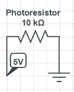
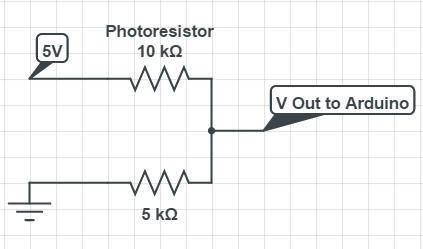
The photoresistor is a light-dependent resistor that reacts to the intensity of light and its resistance decreases with increasing light intensity. It is important to understand that the 10 Kilohm resistor is needed because the Arduino board is measuring changes in voltage when the analogRead() method is called. While the photoresistor is a resistor itself, enabling it to vary voltage, the Arduino would still have issues measuring the voltage changes, since there is no reference point except for Vcc (5V) and Ground. Adding the 10 Kilohm resistor provides a point of reference for the Arduino to measure voltage changes. This additional resistor essentially acts as a voltage divider, allowing the Arduino to convert changes in resistance to changes in voltage. The schematics below illustrate this point:
With Only Photoresistor
With Resistor That Acts As Voltage Divider
The Arduino code for implementing the photoresistor is similar to the code for the previous two analog sensors. First, we declare a constant to identify the photoResistor pin on the Arduino board. Then, in the loop() method we call analogRead() on the photoResistor pin to receive and then process the return values. When the photoresistor is uncovered it typically returns values 800 and above. Likewise, it returns values between 800 and 600, when partially covered and values less than 600 when fully covered.
#include <DHT.h> //https://github.com/adafruit/DHT-sensor-library

const int soilMoisturePin = A0;
const int rainPin = A1;
const int photoResistorPin = A2;

const int tempHumidityPin = 7;
DHT dht(tempHumidityPin, DHT11);
String temperatureCelsius = "";
String temperatureFahrenheit = "";
String humidity = "";


void setup() {
 Serial.begin(9600);

 dht.begin();
}

void loop() {
 int soilMoistureValue = analogRead(soilMoisturePin);
 String soilMoisturePercentValue = String(convertToPercent(soilMoistureValue)) + "%";
 Serial.println(soilMoisturePercentValue);
 delay(1000);

 int rainValue = analogRead(rainPin);
 String rainFall = calculateRainfall(rainValue);
 Serial.println(rainFall);
 delay(1000);

 calculateTempAndHumidity();

 int photoResistorValue = analogRead(photoResistorPin);
 String light = calculateLight(photoResistorValue);
 Serial.println(light);
 Serial.println("n");
 delay(1000);
}

int convertToPercent(int value) {
 int percentValue = 0;
 percentValue = map(value, 1023, 345, 0, 100); //Map values may vary by sensor for 2nd and 3rd parameter
 return percentValue;
}

String calculateRainfall(int rainValue) {
  if (rainValue >= 900) {
    return "No Rain";
  } else if (rainValue >= 700 && rainValue < 900) {
    return "Light Rain";
  } else if (rainValue >= 400 && rainValue < 700) {
    return "Raining";
  } else {
    return "Heavy Rain";
  }
}

void calculateTempAndHumidity() {
  float humidityValue = dht.readHumidity();
  float tempCelsius = dht.readTemperature();
  float tempFahrenheit = dht.readTemperature(true);
  // Sensor readings may be delayed by 2 seconds so wait two seconds between measurements.
  delay(2000);

  if (isnan(humidityValue) || isnan(tempCelsius) || isnan(tempFahrenheit)) {
    Serial.println("Failed to read from DHT sensor!");
  } else {
    temperatureCelsius = String((int) tempCelsius) + (char)223 + "C";
    temperatureFahrenheit = String((int) tempFahrenheit) + (char)223 + "F";
    humidity = String((int) humidityValue) + "%";

    Serial.println(temperatureCelsius);
    Serial.println(temperatureFahrenheit);
    Serial.println(humidity);
  }
}

String calculateLight(int photoResistorValue) {
  if (photoResistorValue > 800) {
      return "Sunny";
  } else if (photoResistorValue >= 600 && photoResistorValue <= 800) {
      return "Cloudy";
  } else if (photoResistorValue < 600) {
      return "Overcast";
  }
}
5. Connect LCD Display

Out of the box, the LCD may not have header pins attached to its connections. If not, simply solder a strip of 16 header pins to the LCD.
- Connect pin 1 on the LCD to the GRD on the breadboard.
- Connect pin 2 on the LCD to the POWER strip on the breadboard.
- Connect pin 4 on the LCD to digital pin 12 on the Arduino. Pin 4 on the LCD is the RS (Register Select) pin, which enables a user to select the instruction mode or the character mode of a LCD.
- Connect pin 5 on the LCD to the GRD on the breadboard.
- Connect pin 6 on the LCD to digital pin 11 on the Arduino. Pin 6 on the LCD is the Enable pin, which is used to tell the LCD that you are sending it data.
- Connect pin 11 on the LCD to digital pin 5 on the Arduino.
- Connect pin 12 on the LCD to digital pin 4 on the Arduino.
- Connect pin 13 on the LCD to digital pin 3 on the Arduino.
- Connect pin 14 on the LCD to digital pin 2 on the Arduino. Pins 11-14 are the dataBus pins on the LCD that will be used to transmit data.
- Connect pin 15 on the LCD to the POWER strip on the breadboard.
- Connect pin 16 on the LCD to the GRD on the breadboard. Pins 15 and 16 on the LCD are used to power the backlight.
- Connect the VCC of the potentiometer to POWER strip on the breadboard.
- Connect the GRD of the potentiometer to the GRD on the breadboard.
- Connect the middle pin of the potentiometer to pin 3 on the LCD. Pin 3 on the LCD is used to adjust contrast via a variable resistor, such as a potentiometer.

The Arduino code for implementing the LCD requires use to import the LiquidCrystal library, which comes with the Arduino IDE upon installation. We then create an LCD object that identifies the RS, Enable, and dataBus pin connections on the Arduino, by calling LiquidCrystal lcd(12, 11, 5, 4, 3, 2);. Next, in the setup() method, we call begin(20,4) on our lcd object. The parameters in this method represent the screen size of the physical lcd. The first parameter is the numerical representation of columns and likewise the second parameter is the numerical representation of rows, therefore, representing a 20 x 4 visual display. In the loop() method, we create a method printToLCD that consumes the readings of all our sensors and displays them on the LCD. Within this method, we initially call lcd.clear() to reset the display by erasing any characters on the screen and re-establishing the cursor at the 0,0 coordinate in the display matrix or top-left corner.
Next, we print values to the LCD by calling lcd.print() and passing in the string that needs to be displayed. The parameterized string should not exceed 20 characters in length, otherwise the entire string will not be displayed on a particular row. Once we have printed values on the first row, we call lcd.setCursor(0,1). This method moves the cursor to the parameterized coordinate. In our case, the first column is on the second row. (It must be noted that the rows and columns are on a zero based index. This is why 0 represents the first column and 1 represents the second row). We continue this pattern in succession until we have printed all our sensor values on the LCD display.
#include <DHT.h> //https://github.com/adafruit/DHT-sensor-library
#include <LiquidCrystal.h>

const int soilMoisturePin = A0;
const int rainPin = A1;
const int photoResistorPin = A2;

const int tempHumidityPin = 7;
DHT dht(tempHumidityPin, DHT11);
String temperatureCelsius = "";
String temperatureFahrenheit = "";
String humidity = "";

LiquidCrystal lcd(12, 11, 5, 4, 3, 2);

void setup() {
  Serial.begin(9600);

  dht.begin();
  lcd.begin(20,4);
}

void loop() {
  int soilMoistureValue = analogRead(soilMoisturePin);
  String soilMoisturePercentValue = String(convertToPercent(soilMoistureValue)) + "%";
  Serial.println(soilMoisturePercentValue);
  delay(1000);

  int rainValue = analogRead(rainPin);
  String rainFall = calculateRainfall(rainValue);
  Serial.println(rainFall);
  delay(1000);

  calculateTempAndHumidity();

  int photoResistorValue = analogRead(photoResistorPin);
  String light = calculateLight(photoResistorValue);
  Serial.println(light);
  Serial.println("n");
  delay(1000);

  printToLCD(temperatureCelsius, temperatureFahrenheit, humidity, light, rainFall, soilMoisturePercentValue);
}

int convertToPercent(int value) {
  int percentValue = 0;
  percentValue = map(value, 1023, 345, 0, 100); //Map values may vary by sensor for 2nd and 3rd parameter
  return percentValue;
}

String calculateRainfall(int rainValue) {
  if (rainValue >= 900) {
    return "No Rain";
  } else if (rainValue >= 700 && rainValue < 900) {
    return "Light Rain";
  } else if (rainValue >= 400 && rainValue < 700) {
    return "Raining";
  } else {
    return "Heavy Rain";
  }
}

void calculateTempAndHumidity() {
  float humidityValue = dht.readHumidity();
  float tempCelsius = dht.readTemperature();
  float tempFahrenheit = dht.readTemperature(true);
  // Sensor readings may be delayed by 2 seconds so wait two seconds between measurements.
  delay(2000);

  if (isnan(humidityValue) || isnan(tempCelsius) || isnan(tempFahrenheit)) {
    Serial.println("Failed to read from DHT sensor!");
  } else {
    temperatureCelsius = String((int) tempCelsius) + (char)223 + "C";
    temperatureFahrenheit = String((int) tempFahrenheit) + (char)223 + "F";
    humidity = String((int) humidityValue) + "%";

    Serial.println(temperatureCelsius);
    Serial.println(temperatureFahrenheit);
    Serial.println(humidity);
  }
}

String calculateLight(int photoResistorValue) {
  if (photoResistorValue > 800) {
      return "Sunny";
  } else if (photoResistorValue >= 600 && photoResistorValue <= 800) {
      return "Cloudy";
  } else if (photoResistorValue < 600) {
      return "Overcast";
  }
}

void printToLCD(String tempCelsius,
                String tempFahrenheit,
                String humidity,
                String light,
                String rain,
                String soilMoisture) {


  lcd.clear();
  lcd.print("Temp: " + tempCelsius + " | " +  tempFahrenheit);
  lcd.setCursor(0, 1);
  lcd.print("Humidity: " + humidity);
  lcd.setCursor(0, 2);
  lcd.print(light + " & " + rain);
  lcd.setCursor(0, 3);
  lcd.print("Soil: " + soilMoisture);
}
All that is left to do now, is upload the sketch to the Arduino and begin monitoring our garden!


In the next Mobile Development For Arduino post, we will connect our prototype to a IFTTT (If This Then That) cloud service so that we can be notified when something in our garden needs attention.