This is the fifth post in a series on mobile development for Arduino. The Internet of Things is transforming society’s concept of the world wide web. What was once an invisible virtual environment has evolved into a tangible physical network of electronic devices. This development has provided an opportunity for a broad spectrum of programmers, ranging from code ninjas to nascent developers, to control their user experience and interaction with the physical world. A more connected world is a more empathetic world and the Internet of Things potentially can improve humanity’s engagement, not only with the environment but each other as well.
In my first three posts, “Mobile Development for Arduino Part 1, Part 2, and Part 3” I provided an introduction to IoT software development using Arduino as a platform. Arduino is an open-source hardware solution, which gives developers an opportunity to cultivate a thorough understanding of electronics and learn how to integrate them using software. In my last post, “Mobile Development for Arduino Part 4”, we began developing a prototype that automates gardening, by acquiring data regarding soil moisture, temperature, humidity, sunlight, and rainfall. In this post, we will build upon our existing prototype by enabling it to communicate remotely with an actuator. This requires several modules to accomplish this:
- RF Transmitter
- RF Receiver
- 5v Relay
- Waterpump Module
- Vinyl Tubing
- Arduino Uno
- Copper Helical Antenna (optional)
- Modules can be acquired at a much lower cost from sites such as Amazon. However, since they source products from different vendors, consistency and quality may vary.
1. Connect RF Transmitter
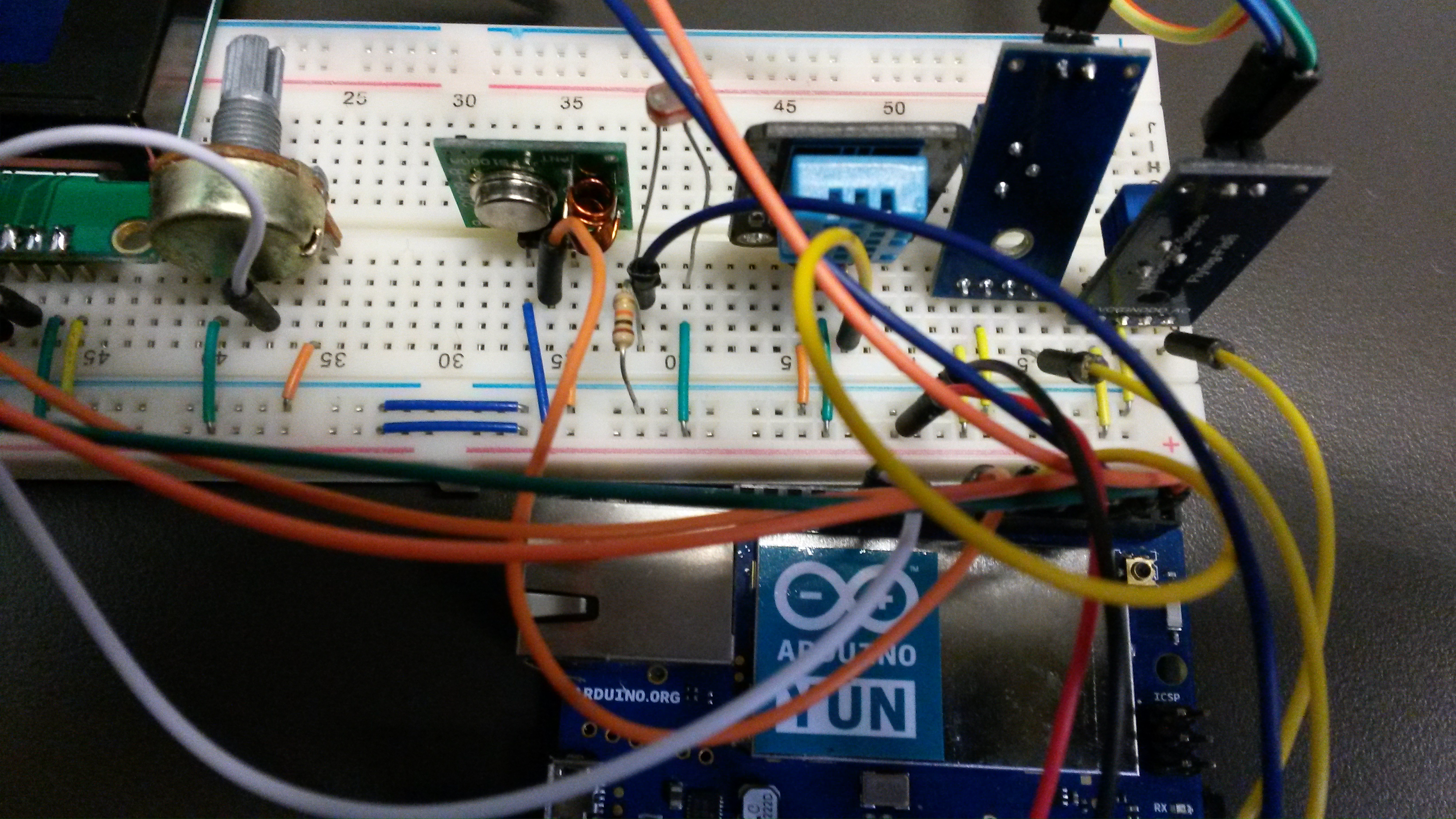
- Connect VCC pin on transmitter to POWER strip on breadboard.
- Connect GRD pin on transmitter to GRD strip on breadboard.
- Connect Signal pin on transmitter to digital pin 8 on Arduino.
- Solder antenna to transmitter (optional).
RF (Radio Frequency) transmitters and receivers are able to communicate at 315 Mhz and 433 Mhz. RF signals can travel long distances and don’t require a direct line of sight to ensure a successful transmission. This makes RF a preferred method of communication in this particular application over mediums such as infrared, which is commonly employed in remote controls for televisions. The caveat to using a RF communication strategy is that if another RF device is communicating on the same frequency as your RF device, you will experience noise and interference. However, this can be mitigated by filtering out RF noise and pairing transmitters and receivers via unique IDs. It is also important to note that the RF transmitter and receiver combo only have an operable range of about 3 feet that can be extended by soldering an antenna to both modules.
Related: Read the first post in the mobile development for Arduino series
In order to use the RF transmitter module, we must import the RadioHead library, which can be downloaded here. In Mobile Development For Arduino Part 4, I discussed how to import 3rd party libraries, so reference that post for guidance about the import process. In addition to importing the RadioHead library, we also need to import the Arduino’s Serial Peripheral Interface (SPI) Library, which the RadioHead library relies upon. This library allows you to communicate with SPI devices with the Arduino as the master device. SPI is a synchronous serial data protocol used by microcontrollers for communicating with one or more peripheral devices quickly over short distances.
#include <RH_ASK.h>
#include <SPI.h>
Now, we need to declare a constant to represent the digital pin the RF transmitter will be using, which is digital pin 8. The next thing we need to do is create a struct that will represent the data that we want to transmit. For simplicity’s sake, our struct will only contain a boolean isOn that will represent whether or not the waterpump is active. Conceivably, this struct could be expanded to suit our needs as long you don’t exceed the 4800 bps data rate. Lastly, we need to create an instance of the RadioHead driver via the RH_ASK class. The default pin for this class to transmit data is digital pin 12. However, since our prototype is already using digital pin 12 to pass serial data to the LCD screen, we need to indicate that our transmit pin is digital pin 8. We can accomplish this by setting the txPin param to 8 and setting the other params to their default values in the RH_ASK class constructor. Documentation for the class can be viewed here.
const int rfTransmitterPin = 8;
struct package {
  boolean isOn;
};

typedef struct package Package;
Package data;
RH_ASK rfTransmitter = RH_ASK(2000, 11, 8, 10, false);
In the setup() method, initialize the rfTransmitter calling init().
void setup() {
 …

  if (!rfTransmitter.init()) {
    Serial.println("init failed");
  }
}
In the loop() method, we need to change the text of LCD display and the content of the data we want to transmit via the RF transmitter based on the reading of the soil moisture sensor. Next, call send on the rfTransmitter to encode and send the data. Lastly, call waitPacketSent() on rfTransmitter to ensure that the data was sent successfully. The waitPacketSent()method is a blocking operation that halts the loop() method and prevents the serial monitor from outputting until the operation has completed.
…
String waterMessage = "";
  if (convertToPercent(soilMoistureValue) < 20) {
      data.isOn = true;
      waterMessage = "& Water On";
  } else {
      data.isOn = false;
      waterMessage = "& Water Off";
  }

  rfTransmitter.send((uint8_t *)&data, sizeof(data));
  rfTransmitter.waitPacketSent();
  Serial.println("RF - Successful Transmission");
...
2. Connect RF Receiver
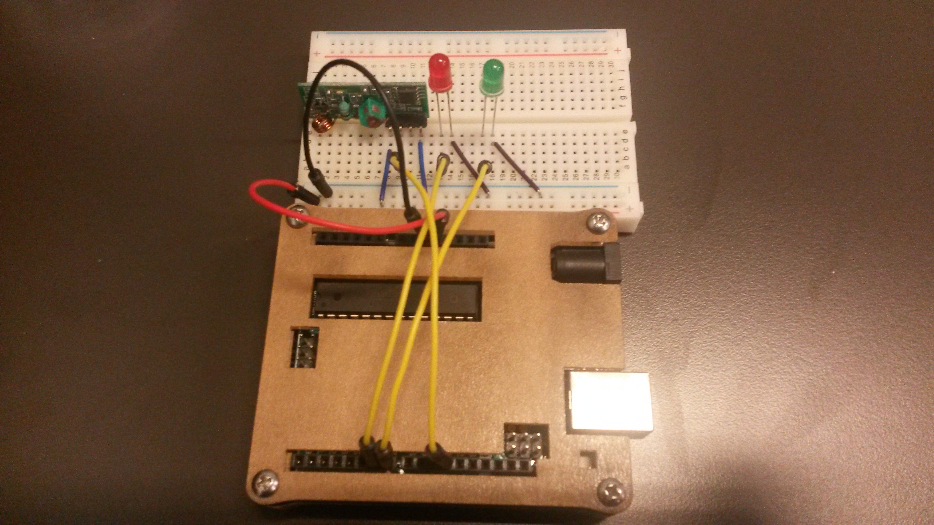
- Connect 5v pin on Arduino to POWER strip on breadboard.
- Connect GRD pin on Arduino to GRD strip on breadboard.
- Connect VCC pin on RF Receiver to POWER strip on breadboard.
- Connect GRD pin on RF Receiver GRD strip on breadboard.
- Connect Data pin on RF Receiver to digital pin 12 on Arduino
- Connect digital pin 6 on Arduino to positive RED LED leg.
- Connect GRD on Arduino to negative RED LED leg.
- Connect digital pin 7 on Arduino to positive GREEN LED leg.
- Connect GRD on Arduino to negative GREEN LED leg.
We need to create a separate sketch file for the RF Receiver since it will be powered by a separate Arduino unit. First, import the RadioHead library and the SPI library. Next, declare an instance of the RF Receiver driver. Notice that for this particular case, we don’t need to use the constructor since the RF Receiver module will be connected to the Arduino via digital pin 12. Next, create constants for the digital pins that correspond to the LED pins and create a global boolean isOn that will be manipulated once transmitted data is received. Lastly, create a struct that mirrors the struct created in the sketch file for the RF transmitter.
#include <RH_ASK.h>
#include <SPI.h>

RH_ASK rfReceiver;

const int redLEDPin = 6;
const int greenLEDPin = 7;

boolean isOn;

struct package {
  boolean isOn;
};

typedef struct package Package;
Package data;
In the setup() method, initialize the rfReceiver, set the digital pins to OUTPUT mode, and set the isOn boolean to false.
void setup() {
    ...

    if (!rfReceiver.init()) {
         Serial.println("init failed");
    }

    pinMode(greenLEDPin, OUTPUT);
    pinMode(redLEDPin, OUTPUT);
    pinMode(waterPumpPin, OUTPUT);

    isOn = false;
}
Related: ESP8266 Programming: Building An IoT Weather Station – Episode 1
In the loop() method, create two buffer variables based on the content and length of our struct that will allow us to decode it once it has been received. Next, we check if the rfReceiver has received any data by calling the available() method. If data has been received, we call the .recv() method on rfReceiver. This method allows us to determine whether or not we have received a valid message by using the two buffer variables that were created earlier. If a valid message has been received, .recv() then proceeds to copy the data to the buffer. Next, we use the memcpy method to take the buffer and save it to our struct object. Next, we read the struct object and set our global isOn boolean based on the response. Lastly, we determine which LED to illuminate based off of our received data.
void loop() {
    uint8_t buf[sizeof(data)];
    uint8_t buflen = sizeof(data);

    if (rfReceiver.available()) {
      Serial.println("RF - Packet Received");
      if (rfReceiver.recv(buf, &buflen)) {
        memcpy(&data, &buf, buflen);
        isOn = data.isOn;
      }
    }

  if (isOn) {
     digitalWrite(greenLEDPin, HIGH);
     digitalWrite(redLEDPin, LOW);

  } else {
     digitalWrite(greenLEDPin, LOW);
     digitalWrite(redLEDPin, HIGH);
  }

}
Related: Read Part 2 in Mobile Development For Arduino
At this point, you should be able to test the prototype and verify that RF transmissions are working as expected. When the soil moisture sensor is submerged in water the green LED should illuminate and the red LED should illuminate when the soil moisture sensor is not submerged.
3. Connect Water Pump Module
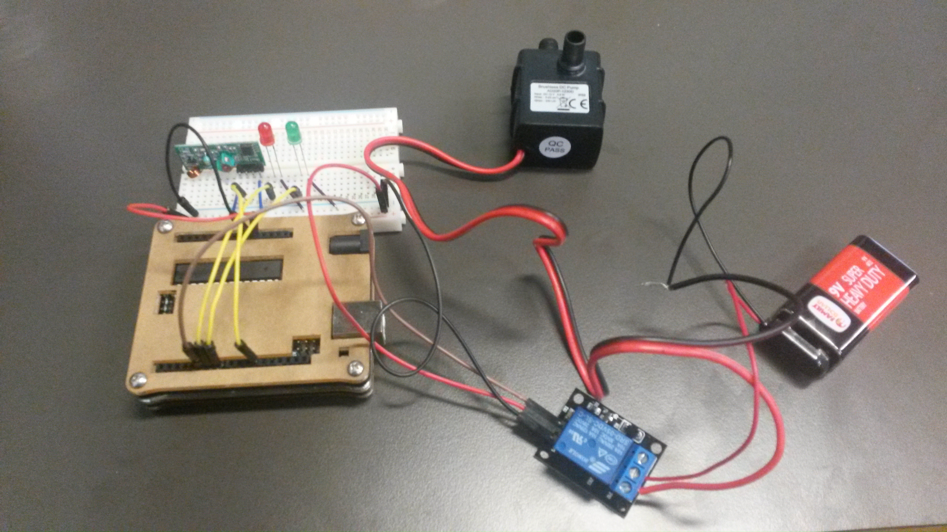
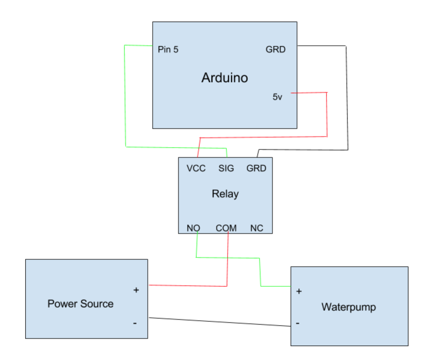
- Connect the Positive cable on the waterpump to Normally Open Connection on Relay.
- Connect the Negative cable on the waterpump to the Negative cable of the power supply.
- Connect the positive cable of the power supply to the Common Connection on the Relay.
- Connect the VCC on Relay to POWER strip on breadboard.
- Connect the GRD on Relay to GRD strip on breadboard.
- Connect the Signal pin on Relay to pin 5 on Arduino.
To grasp what is happening here, it is important to understand that the waterpump requires its own power source since the Arduino cannot supply the necessary power to operate it. Therefore, we must create a separate circuit for the waterpump and connect the waterpump circuit to our RF Receiver circuit via a relay module. A relay is basically an electrically triggered switch. A relay has three connection points, Normally Open Connection, Normally Closed Connection, and Common Connection. Since we want the waterpump to be off by default, we connect it to the Normally Open Connection on the relay. This will initially establish the waterpump circuit in an open state, which will prevent the waterpump from receiving power and running. Once we trigger the relay to flip its switch via Arduino pin digital pin 5 it will close the waterpump circuit and the waterpump will turn on. The diagram below illustrates this.
Related: Read Part 3 in Mobile Development For Arduino
Finally, amend the sketch file to accommodate the addition of the waterpump to the prototype. We have added a boolean isWaterPumpActive to keep the state of the waterpump is sync with the LEDs. Also, the waterpump is easily controlled via the digitalWrite method. Sending HIGH to the relay module turns on the waterpump and likewise sending LOW turns off the waterpump.
#include <RH_ASK.h>
#include <SPI.h>

RH_ASK rfReceiver;

const int waterPumpPin = 5;
const int redLEDPin = 6;
const int greenLEDPin = 7;

boolean isOn;
boolean isWaterPumpActive;

//RF Transmitter
struct package {
  boolean isOn;
};

typedef struct package Package;
Package data;

void setup() {
    Serial.begin(9600);

    if (!rfReceiver.init()) {
         Serial.println("init failed");
    }

    pinMode(greenLEDPin, OUTPUT);
    pinMode(redLEDPin, OUTPUT);
    pinMode(waterPumpPin, OUTPUT);

    isOn = false;
    isWaterPumpActive = false;
}

void loop() {
    uint8_t buf[sizeof(data)];
    uint8_t buflen = sizeof(data);

    if (rfReceiver.available()) {
      Serial.println("RF - Packet Received");
      if (rfReceiver.recv(buf, &buflen)) {
        memcpy(&data, &buf, buflen);
        isOn = data.isOn;
      }
    }

  if (isOn) {
     digitalWrite(greenLEDPin, HIGH);
     digitalWrite(redLEDPin, LOW);

     if(!isWaterPumpActive) {
        isWaterPumpActive = true;
        digitalWrite(waterPumpPin, HIGH); //Turns on Pump
     }

  } else {

     if(isWaterPumpActive) {
        isWaterPumpActive = false;
        digitalWrite(waterPumpPin, LOW); //Turns off Pump
     }

     digitalWrite(greenLEDPin, LOW);
     digitalWrite(redLEDPin, HIGH);
  }

}
All that is left to do now is attach the vinyl tubing to your waterpump, place it in a bucket of water and marvel as it spouts water when it senses that the soil moisture is too low. In the next post, we will connect our prototype to an IFTTT (If This Then That) cloud service so that we can be notified when something in our garden needs attention.

